E120P1010A00 - reader00
So I broke my electronic drum set in my high school junior year. It was a funny story… well, not really. I got pretty tired of trying to MacGyver solutions to try and record me drumming, so I opened up the set controller out of boredom, thinking that I could get it back together and keep playing. News flash: I was pretty bad at keeping electronics intact. But now I had two PCBs loaded with components of mild interest to me.
One PCB was the interface board – it was the board that lit stuff up on the
controller interface. The other one was more interesting. It had
microcontrollers, power supply components, etc. One chip that was particularly
interesting was the MX29GL128FHT2I-90G memory chip that was on the controller
computer board. This thing was, for one, out of stock everywhere and deprecated,
and for two, could have who knows what on it. Actually, it probably just has
audio files. But don’t spoil my fun!
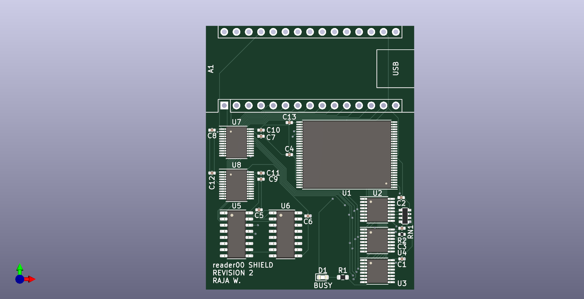
So I designed a circuit (and PCB) with my teeny weeny amount of electrical engineering knowledge to read it, using an Arduino Nano Every (the cheapest Arduino I could find) and as little components I needed to not blow up the memory chip. Okay, it’s not really the minimum components required. I sort of went overboard with the shift registers, but I wanted as much access to the chip inputs as possible.
I bought the PCB and my worst nightmare came true. Actually, it’s probably my like 50th worst nightmare. But it’s still in the top 500. Basically, I went to bed one night at around two ‘o clock in the morning in pretty much a fugue state. I went to check my email (because of course I did) and I realized that the PCB manufacturer I used contacted me about a footprint that was misaligned – from like, two days ago. I frantically responded and then removed the conflicting parts off the board.
The problem arises, however, from the fact that it wasn’t a problem on their
end. I really did just use the wrong footprints for U7 and U8, as I used
the wrong dimensions (4.4mm x 6.5mm instead of the actual, correct dimensions of
4.4mm x 7.8mm that the SN74LVC4245PW actually uses). Huuuagh. Whatever. I still
got some PCBs fabbed.